My Blog
Below are my blog posts. Please use the tags to choose which categories to show.
Design Criteria – HVP – M&I Regenerative Braking
## Overview: ### This design criteria: This design criteria is to help decide the specifications we need for the motors, controllers (inverters if AC motors) and regenerative braking. As such, at the end of each bullet point, where appropriate a [M] or [C] has been appended to the end. This is to show which part of the system it is specific to. If specific to a component but for regenerative braking in particular, (regen) may be added. ### Regenerative braking: The basic concept behind regenerative braking, is the use of the rotational energy of the wheel to generate electrical energy whilst slowing the vehicle down. This allows us to “regain” some of the energy used to speed up the vehicle, instead of losing this as thermal energy using conventional brake pads. We do this by requesting “negative torque” to the controller, which will apply a load over the wheel, thus generating a current which we can use to recharge the battery slightly. Whilst it may not charge by much for a single braking period, the idea is the many braking cycles should add up to a not insignificant amount of energy savings, and potentially allow us to reduce the size of the battery and therefore mass. ### Inputs: - Electrical Energy (AC or DC dependent on motor selection) [M/C] - Cooling (liquid/air dependent on motor and inverter selection) [M/C] - Pedal input (CAN?) [C] - CAN input [C] - Vibration [M/C] - Large and sudden movements [M (part of USM)] - Water & dust from the environment [M] - Some forces from the wheels [M] - Torque (-ve) [M (regen)] ### Conditions: - Process CAN/pedal data and send required power to Motor [C] - Pull power from motor if regen braking requested [C (regen)] - Don’t send too high a voltage to the battery [C (regen)] - Transfer heat from components to coolant [M/C] - Convert electrical energy to torque [M] ### Outputs: - Torque to the wheels [M] - Heat output; Convection and via coolant [M/C] - Unwanted vibrational/sound energy [M] - Feedback motor data to CAN? [C] - Electrical energy back to battery charge circuit [C (regen)] UGR-X24 – High Voltage Powertrain Yuki Suter ## Constraints: ### Geometric: - Whilst HVP would take priority over suspension design, motor should not be too large or difficult in size to design around for the USM team. - Space for the motor controller should be considered, especially since 2 controllers may have to be used depending on which motor-controller configuration we choose. - Space to pass high voltage lines to the outboard motor needs to be considered ### Commercial: - Time constraint due to lead times on the motors and controllers - Financial constraints; Motors and their controllers can be extremely expensive ### Requirements: - Must send appropriate voltage to motors [C] - Must send safe and appropriate power back to battery [C (regen)] - Must be able to withstand a decent amount of stress from the wheel [M] - Must send power to outboards motors in a safe way [C-M] - Must be able to brake without causing lockup [C] ### Rules/Safety: - EV2.2.1 Power limits (+80kW total max permitted for 2 motor RWD) - EV2.2.2 Regenerative braking power is permissible and unrestricted - EV4.3 Separation of Traction System and Grounded Low Voltage System - Important to consider when integrating the controller and motor - Alot of rules in EV4.4.3 must be abided by in order for outboard motors to be permitted (we must follow) ## Goals: - An efficient drivetrain with minimal losses through power conversion etc. - A drivetrain that isn’t overly heavy. (important for motor choice) - Range increase over previous year/FS class entry without sacrificing lap times. - Choice of components should not be overly expensive. This is very important when choosing motors. - As high a ΔRange to ΔMass ratio as possible over previous generations. - Safe integration of outboard motors
UGRacing
Formula Student
Last updated: 15/11/2023

Design Review
Attached is the design review. This was seen by senior members of the team to critique with the intention of solving these problems by the final design report. Feedback listed below: ## Meeting Feedback/Notes APPS - Acceleration Pedal Position Sensor Reasons for 2 not 4 Update peak power for the AMK motors Specific motor type 3 phase AC to motor DC to inverter Field weakening - Back EMF = input voltage at a point - Look into Estimate accu output rather than max motor output - 105a 4 seconds Add link to datasheet to design review Control algorithm of inverter - PWM Add block diagram for m&i No protection for inverter - plans? Design parameters for container - ipX2, Fire retardancy (UL94), high voltage Connectors for container Inverter wiring diagram Current that the inverter can handle USM has made changes - Check if it fits - info avail next week M&I cooling requirements - state them Reasons for regen: - Full efficiency credit from any regen at all - Braking distribution looks to be 70-75% front (72.3%) - Smaller braking system Emergency Braking tests Brake torque from OL into graph data from amk Regen Field Tuning CarMaker model for data OL doesnt give Supercapacitors? - Why or why not Use grip to get braking torque A low enough regen effect would allow for accelerator pedal regen Charging current roughly 102A
UGRacing
Formula Student
Last updated: 14/02/2024

Initial Concept and Analysis
Attached is the final report and analysis of existing systems.
University
Last updated: 23/02/2024
Regenerative Braking Sim
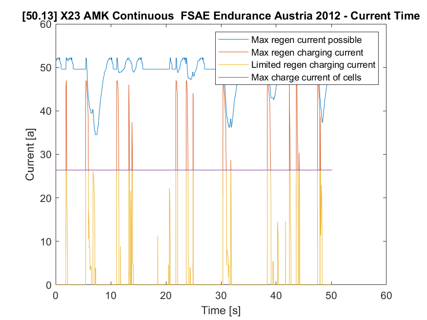
In order to calculate the amount of regen we would be capable of producing, I put some work into utilising the data output from OptimumLap and processing it in MATLAB. ## The Theory I initially hit a dead end on how I was supposed to get “requested brake torque” values. But I soon realised that since the only information inputted into OptimumLap that has to do with braking was the tyre friction coefficients, it must be using those to calculate the brake torques and brake pedal position (the value given in the export data). I couldn’t just assume this however this needed to be validated, hence I set up an OptimumLap simulation that was just a drag strip with an extremely tight curve at the end. What this did is allowed the vehicle to reach max speed, before applying 100% brake torque as the curve was so tight it required a negligible speed to turn the corner. This allowed me to use the deceleration values, along with the weight of the vehicle to calculated the torque on the wheels. Of course due to the downforce of the aerodynamics the torque calculated was higher at higher speeds, but the torque value calculated right at the end of the simulation where the speed was near zero shows the torque as being calculated using the friction coefficients. Another hurdle before I could calculate regenerative braking estimates was the motor statistics. For some bizarre reason AMK does not provide braking data in their datasheet; despite having blank spaces in the datasheet for them. Whilst this meant we had no concrete data on which to base our regen estimates, for most motors the amount of power regenerated is the same as the amount used to achieve the same amount of torque as braked, at that RPM. What this meant is we could use the torque-rpm and power-rpm graphs to calculate the power returned to the inverter. The majority of the inefficiencies during regenerative braking comes from the inverter (its an inverter it is not meant for rectifying), so we applied an arbitrary (again AMK does not provide this information) 80% efficiency to the inverter rectification. With this information, and the maximum charge rate of the cells in mind, some values could be calculated and plotted as below. The MATLAB script can also be found in the attachments at the bottom of this page. ## Results "powerUsed" ⟼ 326.7826Wh "expectedRegen" ⟼ 23.5092Wh "limitlessRegen" ⟼ 33.6483Wh Limitless regen: regen if we werent limited by the charging current (not really relevant to us) ∴ if not limited, >10% regen, otherwise ~7.2% regen. 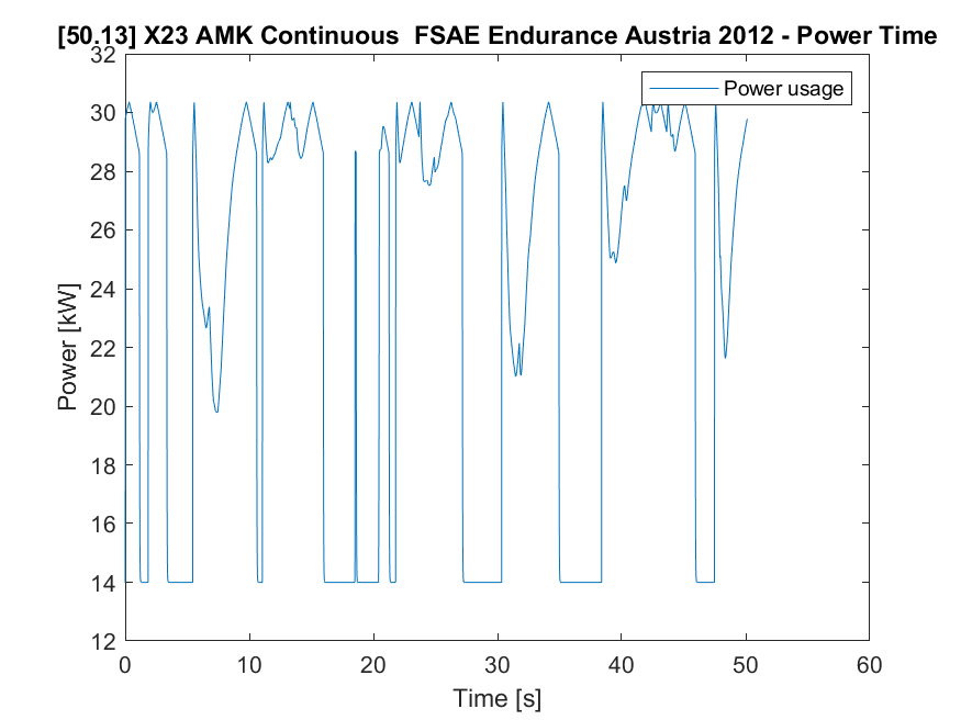 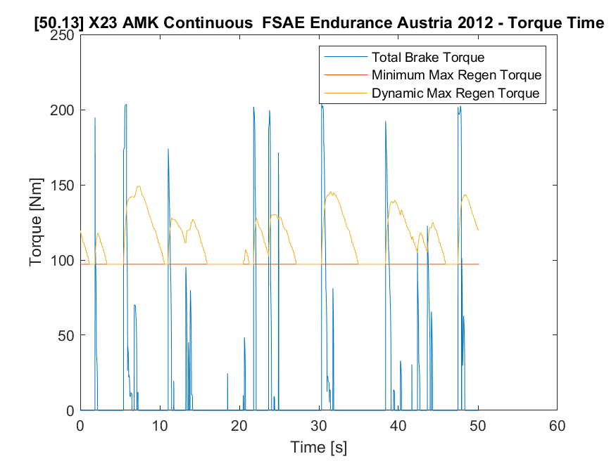  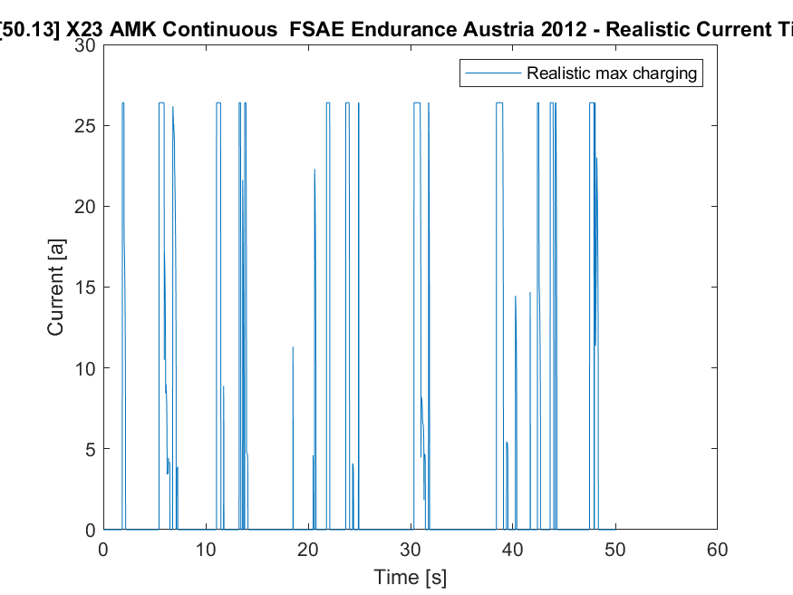
UGRacing
Formula Student
Last updated: 19/03/2024

Design Report
Attached is the final design report for the "Motor & Inverter Selection and Regenerative Braking".
UGRacing
Formula Student
Last updated: 08/04/2024
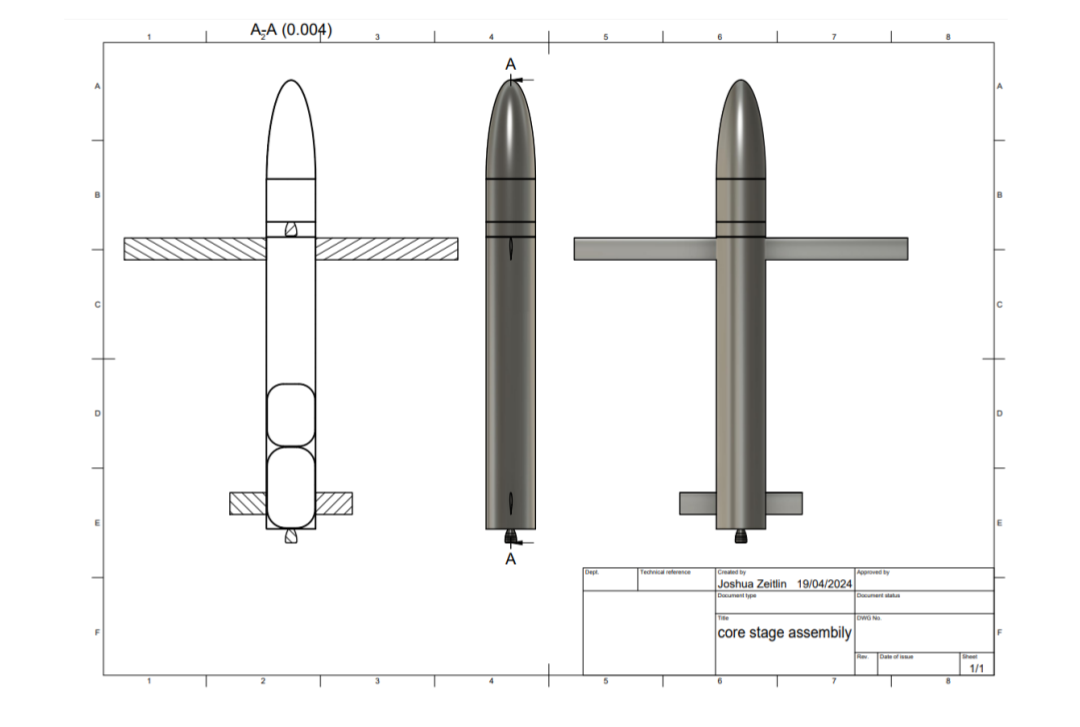
Final Rocket Design Report
Attached is the final report for the aero design project in year 2.
University
Last updated: 19/04/2024
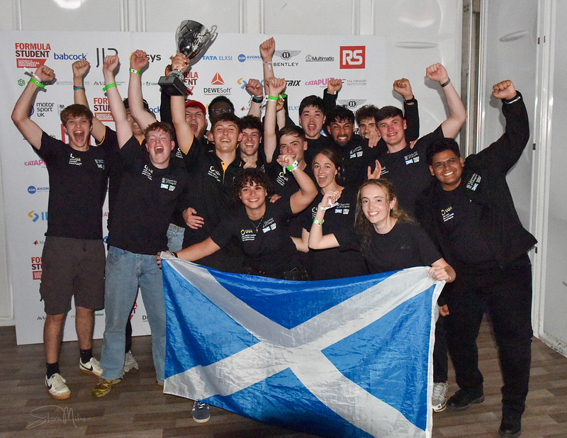
We won!! 🏴🏴🏴
FSUK 2024 Concept Class Win! This summer I had the privilege of representing the University of Glasgow along with my peers from UGRacing, at the IMechE Formula Student competition in Silverstone. Where as a concept sub-team we won 1st place! Winning our class meant to much to everyone on our team. So much time was spent agonising over every part of the car, with long discussions trying to figure out the best possible solution to the many problems we came across. As we were all first year members on the team the learning curve was definitely steep, but with the fantastic support from the FS team and some amazing teamwork, we managed to accomplish something incredible. Accolades aside, the competition was a wonderful learning experience. Getting to talk to many talented student engineers, receiving some brilliant insights from industry professionals, and observing some ingenious solutions to complicated problems made by other teams, there was a lot there to learn from. Congratulations also to the FS team for achieving an impressive 10th place, and the FS-AI Driverless team for securing 3rd place. It was one of the most exciting events I have attended thanks to the hard work by the Institution of Mechanical Engineers and my fellow team members in UGRacing. I cannot wait for what the next year holds, and hope we can continue to find success in next year's competition! ## What’s next? Now that FSUK 2024 is over, the work begins on FSUK 2025. I am now officially out of the concept team and into the main FS team. I intend on staying in the same subteam I was in for concept, the High Voltage Powertrain (HVP) team. Perhaps regenerative braking is on the table? For now though we need to concentrate on getting the Accumulator working and passing scrutineering. Basics first, innovation later. ## Photos 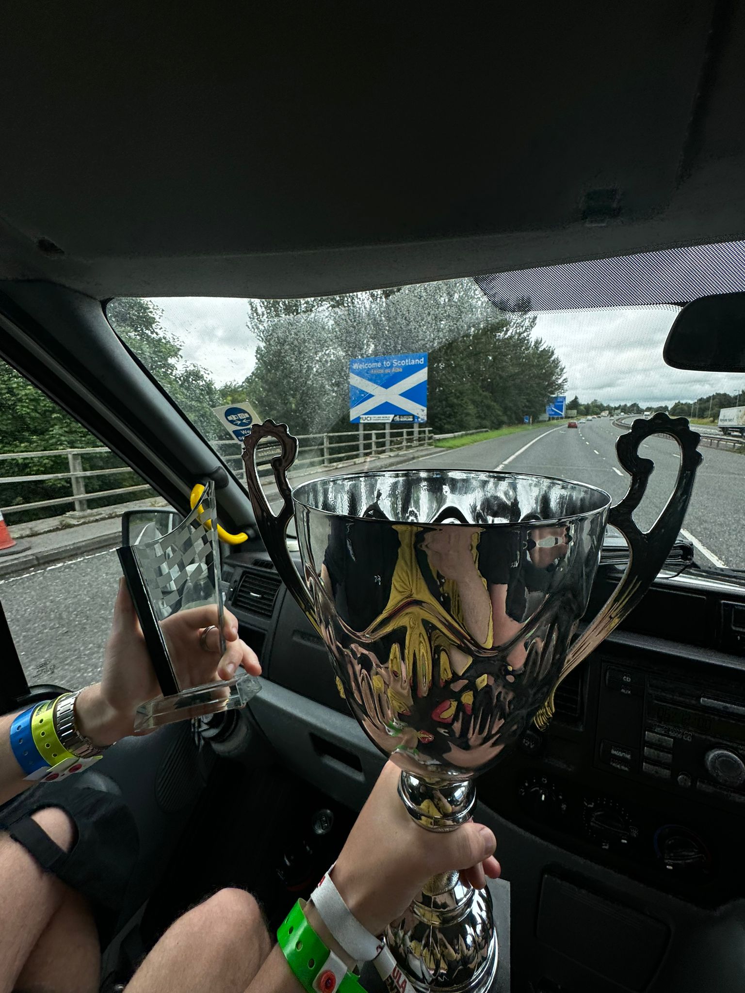 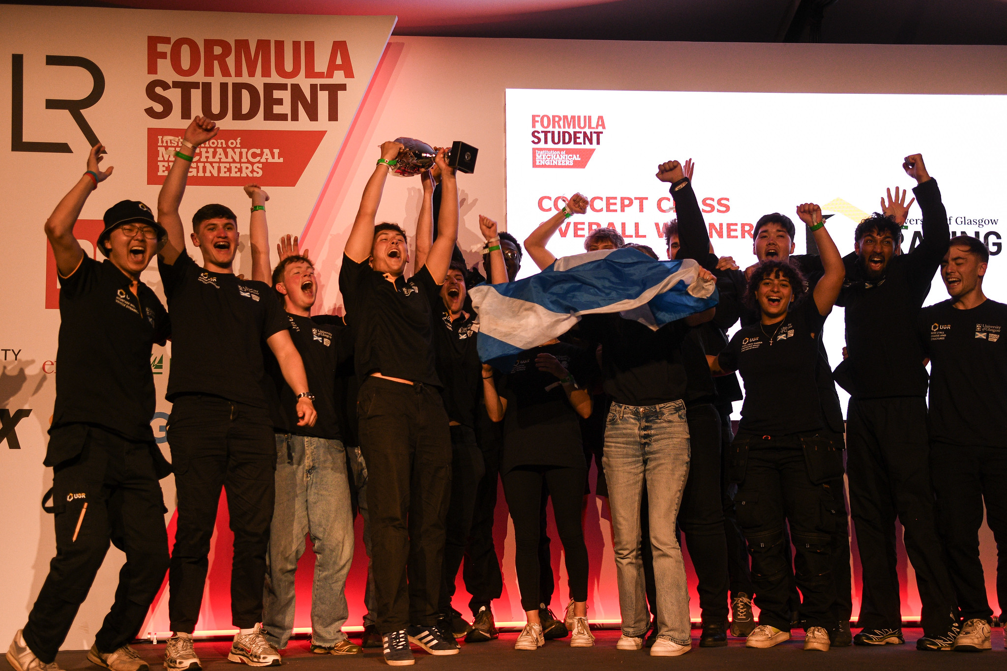 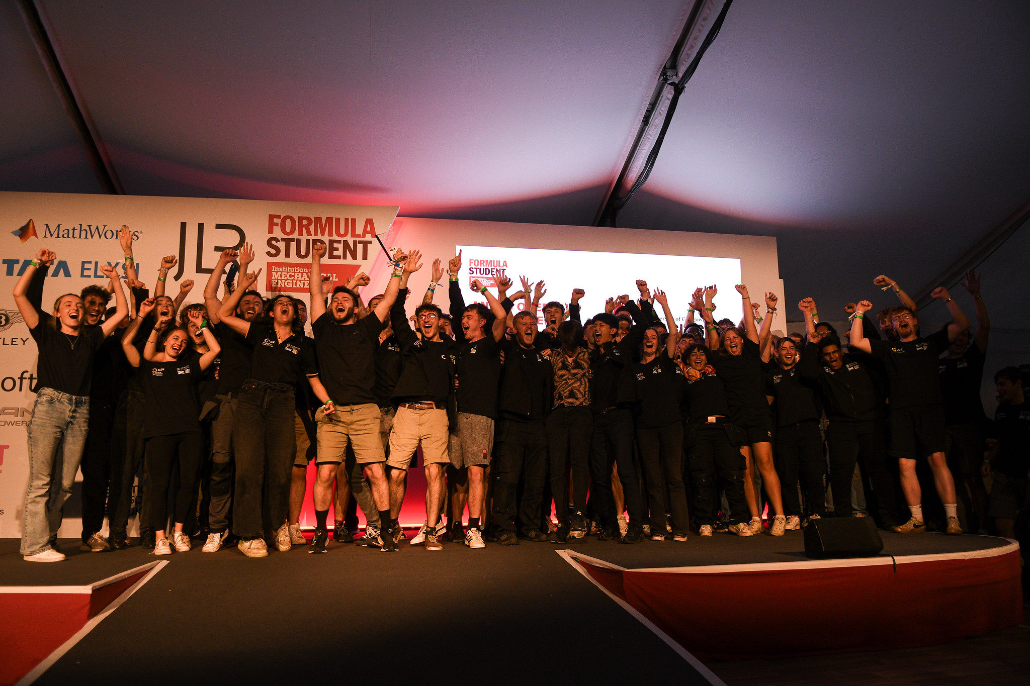
UGRacing
Formula Student
Last updated: 22/07/2024

Hosting this website
This project honestly was never meant to be what I actually use as my portfolio, but just a test of my abilities. I did however surprise myself and get it working so it is what I have stuck with. Anyway, on to how this website is actually hosted. ##Server As I have said above, this was never supposed to be even semi-permanent. I honestly thought I'd give up after about a week, but here we are! Anyway, because of that I didn't want to pay for hosting services (I'm cheap), so I decided to try hosting it myself! A good friend of mine happened to be getting rid of a few workstations whilst I was planning this, which was perfect as it meant I could use them to host this website! Right now this website is running off of one of these workstations running a PROXMOX hypervisor, in a virtual machine running Ubuntu 22.04 LTS server. ##Docker & Watchtower I have a love hate relationship with docker, as I imagine alot of people do. When it works, its great, when I eventually do something I shouldn't have and it breaks, less great. Either way it is something I have been fiddling with for years running various server types (honestly mostly Minecraft servers 🤓), and kind of have the hang of now. To run this website I'm actually running 3 docker containers at once. One is my Django + Gunicorn container, another is my nginx reverse proxy, and my third is an instance of watchtower. What this combination allows me to do is serve the website and static files (using the Django + Gunicorn container) through the nginx reverse proxy. Watchtower is used to monitor my dockerhub repo/image of the Django + Gunicorn container to check for changes. When I push a change to my github repository it builds and pushes the image to dockerhub using github actions, and pings my server's watchtower instance to check for an update. Watchtower then safely shuts down the relevant container if it detects and change and restarts the containers with the new image.